AT Feeding System
An auto transformer is a transformer in which two windings share a common part, where the common part is called a common winding, and the parts in series with the circuit are called series windings.
The product of the voltage and current of the series winding or common winding is known as the self capacity and indicates the size of the AT.
Meanwhile, the capacity that can be supplied to the circuit is called the line capacity.
When the turns ratio is 1:1, the line capacity is two times the self capacity.
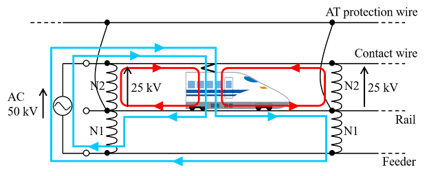
The feeding circuit is configured from feeder lines, overhead contact lines, neutral wires, and auto transformers (AT).
The AT is connected in parallel between the feeder line and the overhead contact line, and the neutral point of the AT is connected to the rail.
When the load current is split between the rails fore and aft of the train and flows to coil N1 of the AT via the neutral point, enough current to cancel out the ampere-turns flows to coil N2.
This indicates that the AT has the effect to draw the return current flowing to the rail.
The converted impedance seen by the secondary side is very low.
The low impedance causes the load current to be drawn off to the left and right ATs.
Consequently, offsetting induced voltages in long telecommunication lines and limiting the section through which current flows to the rail results in reduced inductive interference in the telecommunication lines.
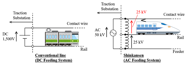
The AT Feeding System has been adopted for most Shinkansen sections.


Comments
Post a Comment