Posts

Showing posts from 2019

Traction Substation (SS)

Image
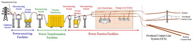
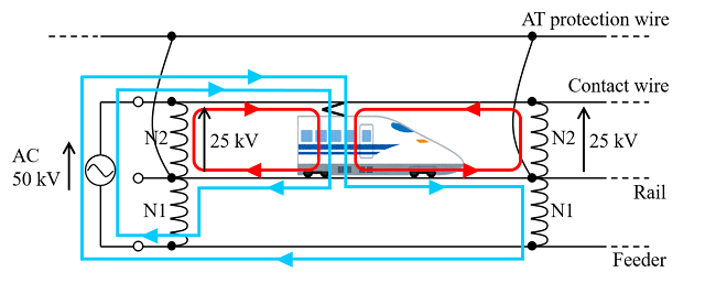
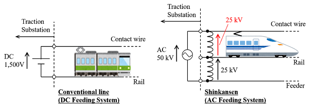
A Traction Substation steps down an AC three-phase power supply to 25 kV, and converts the voltage to two single phases which are then supplied to the overhead contact line. The facilities in the SS are broadly classified into four categories, power-receiving facilities , power transformation facilities , power traction facilities , and remote control facilities. (1)The power-receiving facilities The power-receiving facilities include a power-receiving disconnecting switch , circuit breakers , lightning arresters , voltage transformers , and protective relays . Those facilities are installed for drawing and receiving power via two lines from a three-phase high-voltage bus line of a power  company. (2)The power transformation facilities The power transformation facilities are configured from AC feeding transformers , disconnecting switches and operating transformers or other components. (3)The power traction facilities The power traction facilities are configured from d

Feeding Circuit Configuration

Image
A general configuration of an AC feeding circuit is shown in below figure. Each railway wayside is provided with Traction Substations (SS) , Sectioning Posts (SP) for sectioning of feeding network, Sub-Sectioning Posts (SSP) for limited sectioning of feeding network, and Auto Transformer Post (ATP)  which has only auto transformer. The Traction Substation interval in the case of a conventional line is 30 to 50 km for the BT Feeding System and 90 to 110 km for the AT Feeding System , and in the case of a Shinkansen, 20 to 60 km for the AT Feeding System . And the auto transformer interval is about 10 km for Shinkansen AT Feeding System , so not only SS but also SP, SSP and ATP have the auto transformers.

Summary of Feeding Systems

Image
AT Feeding System (1)Suitable for supplying the electricity to large-capacity loads because the feeding voltage can be made higher than the contact wire voltage. (2)The Traction Substation interval can be made longer than other Feeding Systems. (3)There are n o BT sections . Coaxial Cable Feeding System (1)Exhibits the largest drawing effect due to a large coefficient of mutual induction between coaxial conductors, thereby providing a reduction in telecommunications induction . (2)There are n o BT sections . (3) OCS configuration is simple ; suitable for long tunnels . (4) Cables are costly . Simple Feeding System (1) Simplest feeding circuit configuration . (2)There is a large inductive obstruction on the telecommunication lines (3)Countermeasures such as protection of insulators for flashover are required . (4) The rail potential is theoretically higher than for other Feeding Systems. Simple Feeding System with NF (RC) (1) The feeding circuit i

Simple Feeding System

Image
The Simple Feeding System has the most basic OCS configuration , consisting of overhead contact lines and rails. The Simple Feeding System is economical and ease to maintenance on account of its simple circuit configuration, but in order for a return current to flow to the rail across all sections, there is a large inductive interference in telecommunication lines and a high rail potential which are caused by a leakage current to earth. The Simple Feeding System has therefore been adopted for rolling stock depots , etc. This is because the amount of leakage current flowing to earth is small due to short feeding distance. There is also a system in which a Negative Feeder (NF), which is called "Return Conductor (RC)" globally, is installed parallel to the tracks and is connected to the rail every few kilometers. The NF (RC) fulfils the role of a protective wire and has a slight shielding effect on telecommunication lines .

Coaxial Cable Feeding System

Image
The Coaxial Cable Feeding System is a Feeding System in which coaxial power cables are laid along the tracks and every few kilometres the internal conductor of the coaxial cable is linked to the contact wire while the external conductor is linked to the rail.   In the method, the overhead contact line system (OCS) configuration is straightforward so suitable for narrow sections and tunnel sections . Because the reciprocal impedance of the coaxial cable is about 1/10 in comparison with an aerial system , the load current is drawn off to both terminals of the coaxial cable , providing a telecommunications induction-suppressing effect like that of the AT Feeding System. On the other hand, because the capacitance between the internal and external conductors of the coaxial cable is large , there is a need to investigate a phenomenon whereby the harmonic current is enlarged by the resonance between the capacitance and the inductance on the power supply side. The Coaxial Cabl

AT Feeding System

Image
An auto transformer is a transformer in which two windings share a common part, where the common part is called a common winding , and the parts in series with the circuit are called series windings . The product of the voltage and current of the series winding or common winding is known as the self capacity and indicates the size of the AT. Meanwhile, the capacity that can be supplied to the circuit is called the line capacity . When the turns ratio is 1:1 , the line capacity is two times the self capacity . The feeding circuit is configured from feeder lines, overhead contact lines, neutral wires, and auto transformers (AT) . The AT is connected in parallel between the feeder line and the overhead contact line, and the neutral point of the AT is connected to the rail. When the load current is split between the rails fore and aft of the train and flows to coil N1 of the AT via the neutral point, enough current to cancel out the ampere-turns flows to coil N2. This

Overview of Feeding Systems

Image
In an AC Feeding System, a portion of the return current leaks from the rails to earth via the sleepers, thereby causing an inductive obstruction in telecommunication lines . Therefore, not only a countermeasure on the telecommunication line side, but also a countermeasure on the feeding circuit side for limiting the section in which the return current flows to the rail is taken. The BT Feeding System which uses a Booster Transformer (BT) as a countermeasure in the feeding circuit was adopted at the time of opening the First Shinkansen (Tokaido Shinkansen) . However, the Traction Substation terminal voltage is then low, the  Traction Substation interval is inevitably short , a BT must be provided every 4 km , and an arc is generated by the pantograph in a BT section , and this becomes a drawback in maintaining the overhead contact line. For these reasons, since the Sanyo Shinkansen has started commercial operation, the AT Feeding System using an Auto Transformer (AT)

Frequencies

Image
Electric power network in Japan are 50Hz in Eastern Jap an from Kanto to the North and 60Hz in Western Japan from Chubu to the West, and are divided in the vicinity of Tokaido, with the Fuji river serving as the boundary.   To provide a through operation by means of AC electric cars between the two regions with different frequencies, frequencies must be standardized by ground equipment or dual-purpose 50/60 Hz rolling stock must be used . For the Tokaido Shinkansen , power has been supplied at a uniform frequency of 60Hz by means of ground facilities because of reliability improvements through simplification of the electrical equipment of rolling stock and to achieve lighter rolling stock . However, for the Hokuriku Shinkansen which  has started commercial operation in 1997, a 50/60 Hz dual-purpose rolling stock system was adopted . Reasons are as follows: (1) technological advancements enabled to produce lighter 50/60 Hz dual-purpose rolling stock . (2) a freque

Contact wire voltage

Image
AC feeding voltage of a conventional line (which means "urban train without high-speed") is a single-phase AC voltage of 20 kV, but a standard voltage of the Shinkansen Overhead Contact Line is 50Hz AC voltage of 25 kV . The main reasons for adopting an AC voltage of 25 kV as the standard voltage are as follows: (1) With 1,500 V DC electrification, the collected current is large, the overhead contact line is thick, and the traction substation interval is 3 to 5 km, which means high construction costs . (2) With 1,500 V DC electrification, the power collectors are heavy and tracking during high-speed operation is difficult. (3) With 1,500 V DC electrification, selective shutting off a fault current is difficult because the fault current value and load current value are comparable. (4) Because the Shinkansen is a new line, and tunnels and other facilities are newly provided, sufficient insulation clearance can be secured from the outset, and there are barely any pr